
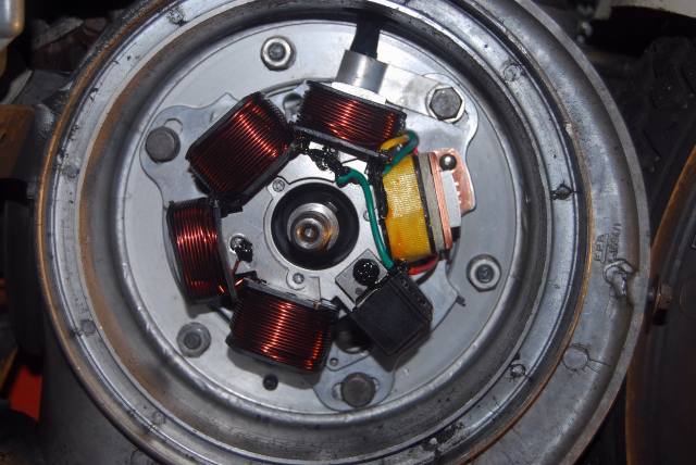
When last we talked about this project, I had removed all the old original parts, and it was time to start putting all the tasty new bits on the scooter.
Here we have the heart of the matter - the stator. I got this stator from Jet200. They have gotten a line of new stators made by BGM in Germany. As you can see in the photo, these things are just great. Having used the Indian-made electronic stators that have been available in the past, I can say with certainty that these German ones are light-years better in terms of build quality. You can see that the coils are very nice and evenly wound, the ignition components are very high quality, and the solders and connections are just top notch. We'll see a bit more as we move through the installation.
So, I installed the stator as you see above. I just loosly put it in place, as I'll need to adjust the stator as I get to the timing later on. I pulled the wiring loom through the hole in the flange at the top, and used a bit of WD40 so it slid through the rubber grommet with ease.
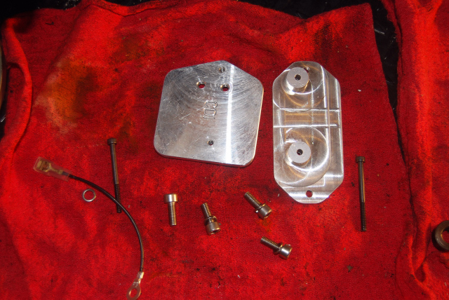
Next, it was time to get things ready for the other electrical components that are needed for the installation. In addition to the stator, I bought a mounting bracket from Jet200. In the past, these were not so readily available, and I just rigged something up to hold the regulator and CDI. However, since Jet200 had these, I opted to try it out. I'm sure glad I did. The mounting brackets are great. These are really nice quality, and come with everything you need for the installation, including all the hardware. You can see in the picture above the two mounting brackets. the one on the right is for the regulator, and the one of the left is for the CDI. You simply use the long allen-head screws provided to attach it through the existing holes in the frame. The brackets have a threaded end for the screws and the other ended is recessed so that the screw heads are flush with the bracket. The other four screws shown in the picture are to attach the regulator and CDI.
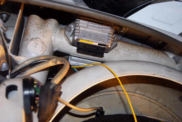
Here is a shot of the regulator mounted to the bracket in the frame. Very tidy.
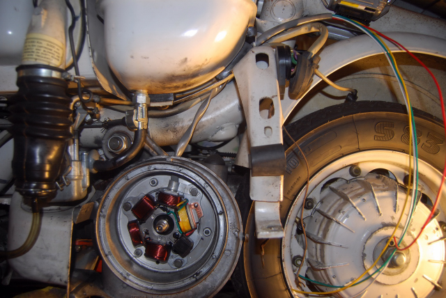
You can see here how the whole thing looks. I took off the black wiring sheath that the loom had on it, and put on the gray sheath that was included with the kit. You may want to use the black sheath if you have a custom application, but on the vintage bikes, they had grey wiring looms. Very nice that the kit came with both colors! You can also notice how long the wires are from the stator. That is also a very nice touch. If you were mounting the electrical components in a different location, it would be good to have the long wires. As it is here, I will have to snip the wires to the correct length.
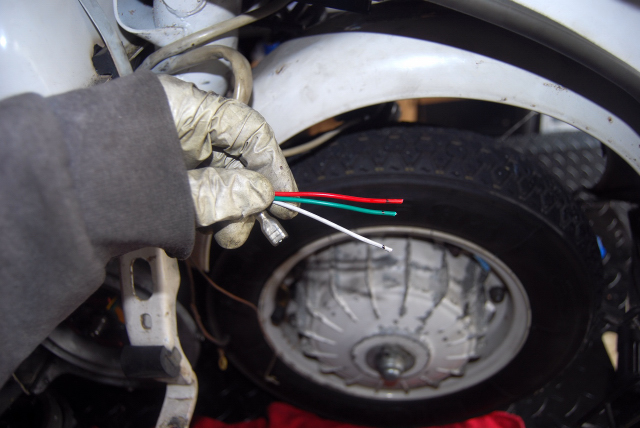
After measuring (twice), I marked the wires with a sharpie, and cut them. You can see the fourth wire already done.
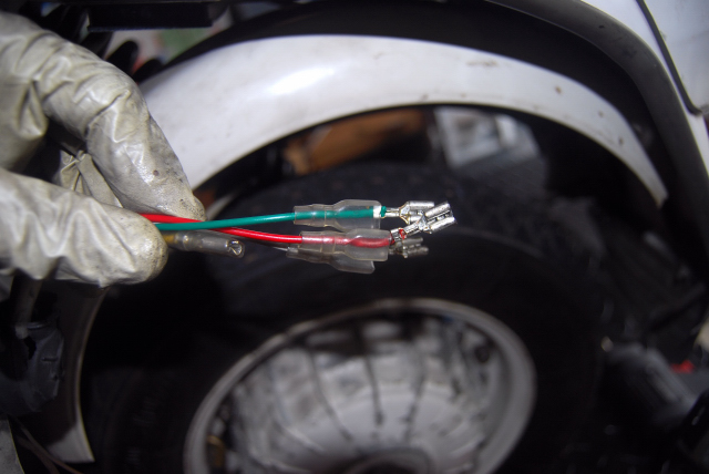
Here are the wires all set to go. The stator included the connectors and the rubber connector covers. Sweet!
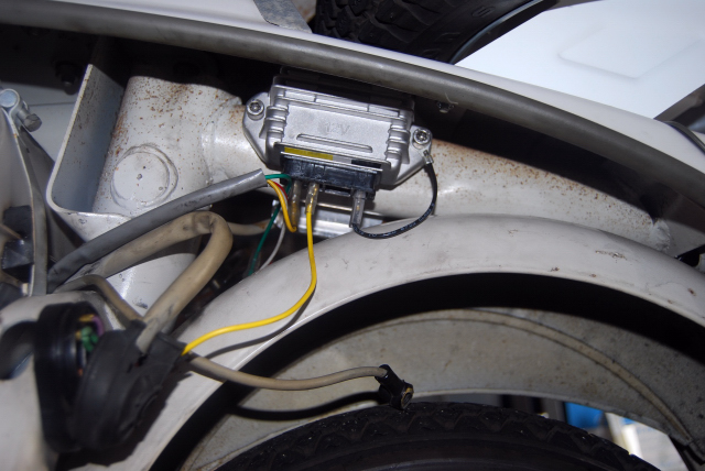
Here you see the wiring loom all connected on the regulator side. The yellow power from the loom is in one of the connectors of the regulator. I fabricated a jumper wire from the regulator output to the main power on the wiring junction box. The other three ignition wires go under the frame tube to the CDI that is located at the other side of the bracket.
In the next installment, I'll fabricate a kill switch wire to the CDI, finish off any wiring, and do the ignition timing... after that, it should be ready to roll!